Weinmann Oxygen MODULE Servicing And Repair Instructions
Module system
Hide thumbs
Also See for Oxygen MODULE:
- Instructions for use manual (68 pages)
Table of Contents
Advertisement
Quick Links
Servicing and
repair instructions
Module System
Oxygen MODULE
WM 22200
Suction MODULE
WM 22220
Combi MODULE
WM 22210
Interface MODULE
WM 22230
Advertisement
Table of Contents

Related Manuals for Weinmann Oxygen MODULE


Summary of Contents for Weinmann Oxygen MODULE
- Page 1 Servicing and repair instructions Module System Oxygen MODULE WM 22200 Suction MODULE WM 22220 Combi MODULE WM 22210 Interface MODULE WM 22230...
-
Page 2: Table Of Contents
6.4.9 Replacing the quick-release 6.2 Oxygen MODULE ....13 coupling ....30 6.2.1... - Page 3 11. Repair and inspection log ....45 11.1Oxygen MODULE ....45 11.2Suction MODULE ....46 11.3Combi MODULE .
-
Page 4: Introduction
Module in terms of function, technology and re- pairs. In conjunction with the training you have al- In 1980, Weinmann launched the first MODULES ready received from Weinmann, you are now a on the market. "trained, qualified expert" and are able to instruct... -
Page 5: Overview
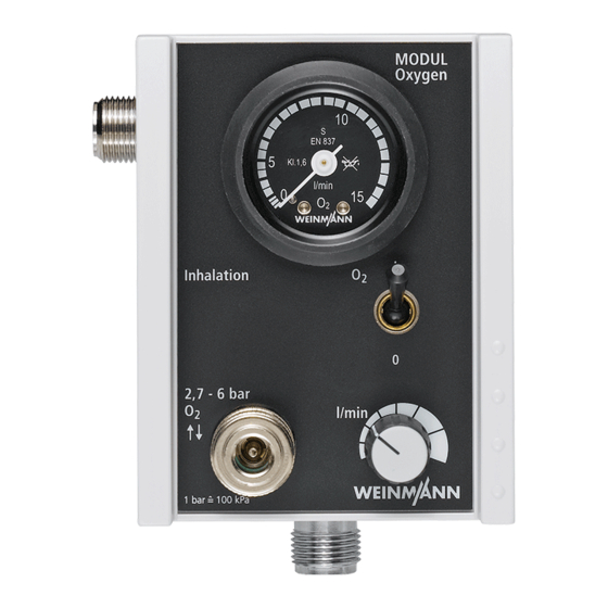
1. Overview Module 1 Oxygen MODULE 1 Suction MODULE M O D U In te rf a b ar 3 Combi MODULE 4 Interface MODULE Connections and controls (on the Combi MODULE) 5 Oxygen inlet with non-return valve 6 Flow dial... -
Page 6: Description
2. Description 2.1 Uses Oxygen Suction Combi Interface MODULE MODULE MODULE MODULE Increase of percentage oxygen volume in – – inspiratory air Creation of a vacuum to aspirate large accumulations of blood, mucus, saliva and solid or – – viscous food from the mouth, the pharyngonasal cavity and the bronchial system. -
Page 7: Final Check
3. Final Check If the final check reveal defects or deviations from the specified parameters, neither the modules nor the OMNIVAC should be used until these defects have been repaired. We recommend you hold reserve stocks of the following items: •... - Page 8 3. Apply approx. 4.5 bar to the input. 4. Set toggle switch to position “1”. 5. Slowly turn pressure regulator until it reads 15 l/min. 6. Close pressure supply. Pressure indication must not fall by more than 0.1 bar/min. Requirement: 7.
-
Page 9: Checking Inhalation Function
3.5 Checking inhalation function MODULE Oyxgen / Combi 1. Connect inhalation outlet to a flowmeter and apply 4.5 bar pressure to the module. 2. Set flow at module to 6 l/min. Reading must not deviate by more than ±0.6 l/min. Requirement: 3. -
Page 10: Checking Aspiration Function
30 seconds. off the manometer directly. In this case it is nec- essary to connect the Weinmann test manometer If this level is not reached, the connections must WM 15294 to vacuum connection be checked for leaks. -
Page 11: Servicing
Remember: a functional check must be performed after every repair. We recommend having all maintenance work, servicing and repairs carried out either by the manufacturer Weinmann or by a qualified technician. 4.1 Intervals The following checks must be carried out to ensure that the modules always function correctly. -
Page 12: Disposal
(see “3.4 Check for leaks in the No vacuum or vacuum too weak system” on page 7) or inadequate O flow for inhala- Moisture in block Replacement by Weinmann tion Module defective or clogged Arrange for repair internally. Noisy inhalation/aspiration... -
Page 13: Repair Information And Repair Instructions
• When you replace components or individual on page 29 and the overview on page 4. parts, please use original Weinmann parts only. 6.2 Oxygen MODULE 6.2.1 Replacing the sieve in the oxygen inlet Tools required: •... -
Page 14: Replacing The O-Ring In The Oxygen Outlet
Open-ended spanner SW 19 (only with AGA coupling), • Open-ended spanner SW 22, • Guide pipes, for toggle switches (from Weinmann), • Special locknut tool G 3/8 and special tool from Set WM 15348. 1. Twist the knob as far as it will go to the left so that you will have a reference point later on when assembling. - Page 15 8. Clamp the special locknut tool in a vice with protective jaws. 9. Tighten the nuts of the special locknut tool against the inhalation connection using an open-ended spanner (SW 22). 10. Turn entire housing to left to undo connection If it is not possible to undo connection , pro- ceed as described from step...
-
Page 16: Assembling The Housing
Open-ended spanner SW 19 (only with AGA coupling), • Open-ended spanner SW 22, • Guide pipes, for toggle switches (from Weinmann), • Special locknut tool G 3/8 and special tool from Set WM 15348. 1. Wet the edge of the pressure gauge... - Page 17 10. Screw the swivel screw connection onto the Illustration of subsequent installation position pressure gauge using an open-ended span- ner (SW 7). Take care to ensure the correct installation posi- tion. The tube must not protrude beyond the hous- ing afterwards. Pneumatic block 11.
- Page 18 18. Clamp the special locknut tool in a vice. 19. Loosen the nuts of the special locknut tool using an open-ended spanner (SW 22). 20. Remove the module from the vice and unscrew the special locknut tool. 21. Fasten the knob onto the front of the device: –...
-
Page 19: Replacing The Non-Return Valve In The Distributor Block
6.2.5 Replacing the non-return valve in the distributor block Tools required: • Crosstip screwdriver, size 1, • Open-ended spanner SW 22, • Brass brush, • Thread tapper M 10 x 1 for internal thread, • Special locknut tool G 3/8, special spanner SW 20 with handle bar from Set WM 15348. 1. -
Page 20: Replacing The Pressure Gauge
6.2.6 Replacing the pressure gauge Tools required: • Crosstip screwdriver, size 1, • Open-ended spanner SW 7. 1. Unscrew the base section of the housing (see steps in chapter ”6.2.3 Dismantling the housing“ on page 14). 2. Using an open-ended spanner (SW 7), re- lease the swivel screw connection from the pressure gauge... -
Page 21: Replacing The Tubes
6.2.7 Replacing the tubes Tools required: • Crosstip screwdriver, size 1, • Bulldog end cutting nippers, • Open-ended spanner SW 7, • Small slotted screwdriver or flat object for bending the single-lug clips. 1. Unscrew the base section of the housing (see steps in chapter ”6.2.3 Dismantling the housing“... -
Page 22: Replacing The Toggle Switch
Open-ended spanner SW 17, • Open-ended spanner SW 19 (only with AGA coupling), • Guide pipes, for toggle switches (from Weinmann), • Special locknut tool G 3/8 and special tool from Set WM 15348. 1. Remove the housing (see “6.2.3 Dismantling the housing”... -
Page 23: Replacing O-Ring Of Walther Coupling
3. Remove the coupling: – Unscrew the Walther coupling using an open-ended spanner (SW 14). As the coupling is secured with Loctite 245, this will take a little strength. – If your Module is equipped with an AGA coupling, unscrew it using the open-ended spanner (SW 19). -
Page 24: Replacing The Pressure Regulator
Open-ended spanner SW 7, • Open-ended spanner SW 19 (with AGA coupling), • Guide pipes, for toggle switches (from Weinmann), • Special locknut tool G 3/8 and special spanner SW 14.2 from Set WM 15348, • Special socket wrench with cross-bar for pressure regulator WM 22392. - Page 25 3. Place the special spanner SW 14.2 over both nuts of the pressure regulator and unscrew them. 4. Screw down the new pressure regulator gether with the seal in the pneumatic block. 5. Fit the spindle limiter screw cap as follows: –...
-
Page 26: Suction Module
6.3 Suction MODULE 6.3.1 Replacing the sieve in the oxygen inlet See ”6.2.1 Replacing the sieve in the oxygen inlet“ on page 13. 6.3.2 Replacing the O-ring in the oxygen outlet See ”6.2.2 Replacing the O-ring in the oxygen outlet“ on page 14. 6.3.3 Dismantling the housing See ”6.2.3 Dismantling the housing“... -
Page 27: Replacing The Non-Return Valve In The Distributor Block
6.3.5 Replacing the non-return valve in the distributor block See “6.2.5 Replacing the non-return valve in the distributor block” on page 14. Important! Please observe the exceptions for assembling the housing under • ”6.3.4 Assembling the housing“ on page 26. 6.3.6 Replacing the pressure gauge See ”6.2.6 Replacing the pressure gauge“... -
Page 28: Replacing The Toggle Switch
6.3.8 Replacing the toggle switch See ”6.2.8 Replacing the toggle switch“ on page 22. Important! Please observe the exceptions for assembling the housing under • ”6.3.4 Assembling the housing“ on page 26. 6.3.9 Replacing the quick-release coupling See ”6.2.9 Replacing the quick-release coupling“ on page 22. Important! Please observe the exceptions for assembling the housing under •... -
Page 29: Combi Module
6.4 Combi MODULE 6.4.1 Replacing the sieve in the oxygen inlet See ”6.2.1 Replacing the sieve in the oxygen inlet“ on page 13. 6.4.2 Replacing the O-ring in the oxygen outlet See ”6.2.2 Replacing the O-ring in the oxygen outlet“ on page 14. 6.4.3 Dismantling the housing See ”6.2.3 Dismantling the housing“... -
Page 30: Replacing The Non-Return Valve In The Distributor Block
6.4.5 Replacing the non-return valve in the distributor block See ”6.2.5 Replacing the non-return valve in the distributor block“ on page 19. Important! Please observe the exceptions for dismantling and assembling the housing under • ”6.4.3 Dismantling the housing“ on page 29, •... -
Page 31: Replacing The Pressure Regulator
6.4.10 Replacing the pressure regulator See ”6.2.11 Replacing the pressure regulator (MODULE Oxygen: up to Device No. 1616; MODULE Combi: up to Device No. 1075; MODULE Suction: up to Device No. 1010)“ on page 24. Important! Please observe the exceptions for dismantling and assembling the housing under •... -
Page 32: Interface Module
6.5 Interface MODULE 6.5.1 Replacing the sieve in the oxygen inlet See ”6.2.1 Replacing the sieve in the oxygen inlet“ on page 13. 6.5.2 Replacing the O-ring in the oxygen outlet See ”6.2.2 Replacing the O-ring in the oxygen outlet“ on page 14. 6.5.3 Dismantling the housing See ”6.2.3 Dismantling the housing“... -
Page 33: Replacing The Non-Return Valve In The Distributor Block
6.5.5 Replacing the non-return valve in the distributor block See ”6.2.5 Replacing the non-return valve in the distributor block“ on page 19. Important! Please observe the exceptions for dismantling and assembling the housing under • ”6.5.3 Dismantling the housing“ on page 32, •... -
Page 34: Replacing The Quick-Release Coupling
6.5.8 Replacing the quick-release coupling See ”6.2.9 Replacing the quick-release coupling“ on page 22. Important! Please observe the exceptions for dismantling and assembling the housing under • ”6.5.3 Dismantling the housing“ on page 32, • ”6.5.4 Assembling the housing“ on page 32. Interface MODULE... -
Page 35: Spare Parts
7. Spare parts 7.1 Spare parts list Note: The item numbers in the following table match the numbers in the text of these service and repair instructions and the instructions for use. Item no. Designation Order No. Threaded connection, pre-assembled WM 22339 Pressure gauge –... - Page 36 Item no. Designation Order No. Sieve set WM 15284 consisting of 2 seals and 1 sieve Set of fixing components consisting of: – O-ring 8 x 4 WM 15288 – Raised countersunk head screw M4 x 10 DIN 966 – Protective washer Ø 4 –...
-
Page 37: Spare Parts Required For Servicing
• Seal 4x8x0.5 • Non-return valve, assembled • O-ring 6x2 • 2 port / 2 position valve • Set of tubes Service pack Oxygen Module 8 years WM 15409 comprising: • Sieve • Seal 4x8x0.8 • Seal 3.5x6x0.5 • Seal 4x8x0.5 •... - Page 38 Service pack Combi Module 8 years WM 15411 comprising: • Sieve • 3 port / 2 position valve (WM 22590 MODULE Oxygen) • Seal 3.5x6x0.5 • Seal 4x8x0.8 • Non-return valve, assembled • Seal 4x8x0.5 • 2 port / 2 position valve (WM 22258 MODULE Oxygen) •...
-
Page 39: Tools And Test Equipment
Below is a list of all tools and test equipment used in these service and repair instructions. The particular tools and test equipment required are outlined in each respective chapter. Special tools can be purchased from the manufacturer Weinmann. 8.1 General tools •... -
Page 40: Test Equipment
8.3 Test equipment • Set of test pressure gauges, • Flowmeter 0 - 20l, vacuum WM 15294 e.g. Yokogawa • Pressure gauge 0 – 6,3 bar, class 1.6 Type WIKA Type EKU VIP-Ventilatortester obtainable from: obtainable from: Alexander Wiegand GmbH & Co. EKU Elektronik GmbH Alexander-Wiegand-Strasse 30 Feldstrasse 9a... -
Page 41: Technical Data
9. Technical data Oxygen MODULE Suction MODULE Combi MODULE Interface MODULE Product category according to 93/42/EEC Dimensions 100 x 125 x 90 100 x 130 x 90 100 x 172 x 90 L x B x H in mm Weight 0.9 kg... -
Page 42: External Oxygen Flow Volume
Oxygen input External oxygen flow volume 2.7 bar dynamic operating not less than 70 l/min pressure at 80 l/min from Weinmann pressure reducer not less than 100 l/min WM 1102/106 from Weinmann pressure not less than 90 l/min reducer WM 30301... -
Page 43: Aspiration Efficiency
9.3 Aspiration efficiency Maximal suction The maximal suction exerted by the Combi and Suction MODULES depends on the input pressure of the oxygen supply. The data below are valid for a 2 litre aspirate bottle. Input pressure p2 Max. vacuum Maximal suction Oxygen consumption 2.7 bar... -
Page 44: Technical Changes
10. Technical Changes Technical change From Device No. Date With screw cap WM 20522 1618 17.08.98 White cap 2396 15.01.99 Counter nut V2A WM 22226 2896 07.05.99 New screw cap WM 22234 4096 10.01.00 Reinforcement for lower part of housing 14101 17.05.04 Technical Changes... -
Page 45: Repair And Inspection Log
11. Repair and inspection log 11.1 Oxygen MODULE Repair and inspection log... -
Page 46: Suction Module
11.2 Suction MODULE Repair and inspection log... -
Page 47: Combi Module
11.3 Combi MODULE Repair and inspection log... -
Page 48: Interface Module
11.4 Interface MODULE Repair and inspection log... - Page 52 For decades Weinmann has been developing, producing and marketing medical devices for markets around the world. In cooperation with our partners we design economic health systems for diagnosis and therapy in Sleep Medicine, Home Mechanical Ventilation, Oxygen Medicine and Emergency Medicine.